Example: PFR Reactor with Recycle
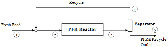
This example illustrates the process of modeling a PFR reactor in which one or more compounds are recycled, as shown in the following figure.
Here, the Fresh Inlet  is mixed with the Recycle stream
  ; the resulting stream
  enters the PFR reactor and stream
  is the reactor effluent. Stream goes to a separation process from which the Recycle stream is returned to the inlet, and the final system outlet is stream
Both Estimation and Optimization modes are considered next. In order to follow this example, please first import the PFR_withRecycle_Example.rex file from the Optience Corporation\REX Suite\REX Examples folder. If you upgraded from a previous version of REX, you may find the examples folder one level above in the Optience Corporation\REX Examples folder located in your installation directory.
Mode Estimation
|
|---|
is mixed with the Recycle stream ; the resulting stream enters the PFR reactor and stream is the reactor effluent. Stream goes to a separation process from which the Recycle stream is returned to the inlet, and the final system outlet is stream Both Estimation and Optimization modes are considered next. In order to follow this example, please first import the PFR_withRecycle_Example.rex file from the Optience Corporation\REX Suite\REX Examples folder. If you upgraded from a previous version of REX, you may find the examples folder one level above in the Optience Corporation\REX Examples folder located in your installation directory.
Consider a simple system with compounds A, B and C (C being an inert), in which only the following reaction takes place:
As you will see in the example project, the compounds, reactions and their kinetics parameters are entered as usual in the REX nodes.
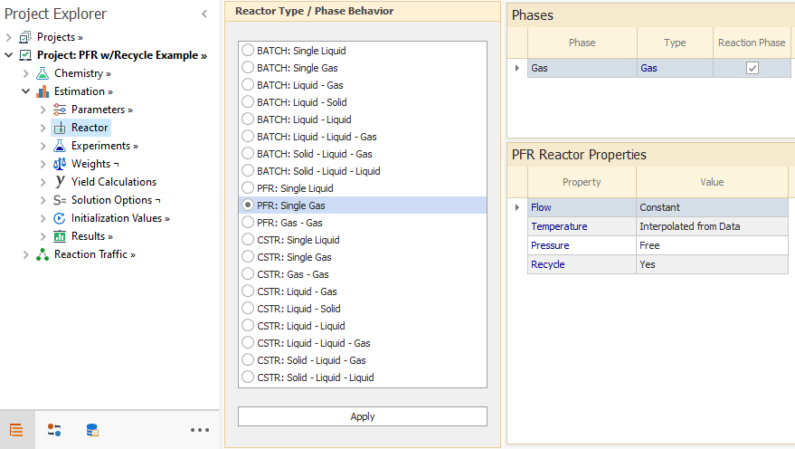
The specification of recycle starts in the Reactor Node, where the Recycle option is enabled in the first grid of the Reactor node:
As you may see in the figure above, the Flow is specified as Constant, Temperature along the PFR reactor as Interpolated from Data, and Pressure as Free.
In the Experiments node, three experimental sets are defined:
Set1: A set with no recycle with two datapoints corresponding to fresh inlet and final outlet.
Set1-Rec: A set with recycle with two datapoints corresponding to fresh Inlet and final outlet .
Set2-Rec: A set with recycle and intermediate datapoints containing reactor temperature profile.
When loading the experimental information into the sets, you must take into account that for a recycled PFR reactor, the first Datapoint corresponds to the Fresh Feed stream, and in the last included Datapoint, you must load the variables values measured at .
The last included datapoint is the only one in each set, for which the reconciliation of variables may be carried out. In the case of having more than two included Datapoints in a given set (as in the Set2-Rec in the example), the only information in those intermediate Datapoints that are actually used in the model are Temperature and/or Pressure, if these variables are chosen as Interpolated in the second grid of Reactor node.
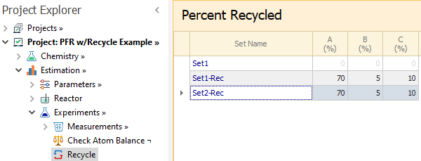
The recycle percentages are entered in the Recycle node. Here, we specify the molar percent of each compound that is recycled back: Set1 without any recycle, and the other sets with recycle percent values of (70% of A, 5% of B and 10% of C):
Display of Results: Compounds
After running the project, you will see more options to view the compound profiles in the Results subnodes as shown in the following figure.
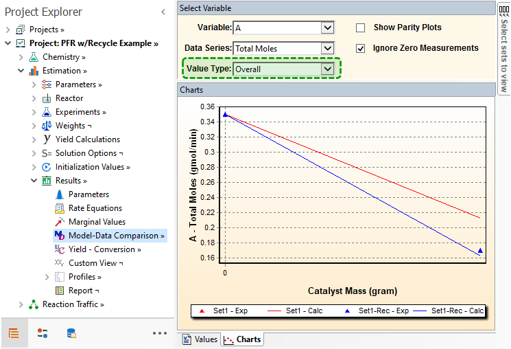
For instance, when displaying the information for Set1 and Set1_Rec only and choosing compound A in Model-Data Comparison node, you will notice the Value Type column, which only appears for this recycled reactor. The default here is Overall, implying that the information displayed corresponds to and only:
Both sets have the same Fresh Inlet composition, therefore the first points displayed coincide. The amount of A finally leaving the PFR&Recycle system is smaller in the second set due to the recycle.
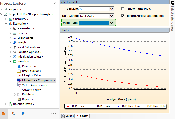
When you select PFR in the Value Type column, the values internal to the PFR are displayed.
The values of the reactant A along the reactor are higher in the second set, since A is recycled.
The description above applies to the Model-Data Comparison node, and to the compounds or conserved pseudo-compounds shown in the Yield-Conversion node. When Value Type=Overall, the yields and conversions at with respect to are shown. If Value Type=PFR, the yields and conversions along the reactor with respect to the PFR's inlet are shown.
Display of Results: Flow
In the example, Flow was chosen as Constant in the Reactor node. This constant flow is calculated based on the summation of the fresh feed and calculated recycle stream flows, and is kept constant, as you can see by going to the Charts tab in Model-Data Comparison node and selecting Value Type as PFR.
You will notice that for Set1, the set with no compounds recycled, the Flow value along the reactor is the same as the entered in the Datapoint. For Set1-Rec the flow is also constant but higher, due to the mix of streams and that enters to the PFR reactor as . To obtain this flow value within the reactor, it is assumed that Temperature and Pressure are the same for and , thus the relation between their flows is the same as the relation between the total amount of compounds moles in them.
The same assumption is considered to obtain the Flow in, whose value can be seen by switching Value Type to Overall. As Pressure and Temperature are considered to be the same in and , then the relation between their flows is proportional to the relation of the sum of compounds moles in them. For constant or interpolated pressure reactors which are more common, the flow is automatically calculated based on the pressure specifications.
Display of Results: Temperature
When Temperature is selected as Constant or Interpolated from Data in the Reactor node, it is assumed that the temperature at is the same as in (so no heat balance is done when mixing and ). Similarly, streams and have the same temperature.
Because of this, the temperature entered in the first datapoint is also the temperature at the reactor's inlet. If temperature is interpolated, as in the example, then the value of temperature entered in the last datapoint is the temperature at the reactor's end; and the values along the reactor are obtained by linear interpolation.
In case of having more intermediate datapoints, as it happens in Set2_Rec, the linearly interpolated values are obtained by considering the adjacent Datapoints, as you can see by including Set2_Rec in Model-Data Comparison node and then viewing the Charts subnode.
On the other hand, if the Use Energy Balance option is enabled for Temperature calculations in the Reactor node, heat balance equations are applied to calculate the temperature of stream from mixing streams and . As for the reactor outlet, it is assumed that temperature for streams and is same as for .
You may try the energy balance option by switching the Temperature to Use Energy Balance and then run the model. The values loaded in Chemistry → Compounds → Properties node shows the only reaction to be exothermic. You will notice in Model-Data Comparison node when Value Type=Overall is chosen, that temperature for all the sets is 25C in, as that is the experimental value loaded for all sets in the first datapoint in Experiments → Measurements → Sets node.
However, when switching to Value Type=PFR, temperature for Catalyst Mass = 0 ( stream) is 25C only for Set1, as that set has no recycle. For the other sets, the value there is different, resulting from the mix of recycled stream with fresh feed.
Top of Topic

|
|---|
The specification of recycle starts in the Reactor Node, where the Recycle option is enabled in the first grid of the Reactor node:
|
|---|
As you may see in the figure above, the Flow is specified as Constant, Temperature along the PFR reactor as Interpolated from Data, and Pressure as Free.
In the Experiments node, three experimental sets are defined:
Set1: A set with no recycle with two datapoints corresponding to fresh inlet and final outlet.
Set1-Rec: A set with recycle with two datapoints corresponding to fresh Inlet
and final outlet .Set2-Rec: A set with recycle and intermediate datapoints containing reactor temperature profile.
When loading the experimental information into the sets, you must take into account that for a recycled PFR reactor, the first Datapoint corresponds to the Fresh Feed stream
, and in the last included Datapoint, you must load the variables values measured at . The last included datapoint is the only one in each set, for which the reconciliation of variables may be carried out. In the case of having more than two included Datapoints in a given set (as in the Set2-Rec in the example), the only information in those intermediate Datapoints that are actually used in the model are Temperature and/or Pressure, if these variables are chosen as Interpolated in the second grid of Reactor node.
The recycle percentages are entered in the Recycle node. Here, we specify the molar percent of each compound that is recycled back: Set1 without any recycle, and the other sets with recycle percent values of (70% of A, 5% of B and 10% of C):
|
|---|
Display of Results: Compounds
After running the project, you will see more options to view the compound profiles in the Results subnodes as shown in the following figure.
For instance, when displaying the information for Set1 and Set1_Rec only and choosing compound A in Model-Data Comparison node, you will notice the Value Type column, which only appears for this recycled reactor. The default here is Overall, implying that the information displayed corresponds to
and only:
|
|---|
Both sets have the same Fresh Inlet composition, therefore the first points displayed coincide. The amount of A finally leaving the PFR&Recycle system is smaller in the second set due to the recycle.
When you select PFR in the Value Type column, the values internal to the PFR are displayed.
|
|---|
The values of the reactant A along the reactor are higher in the second set, since A is recycled.
The description above applies to the Model-Data Comparison node, and to the compounds or conserved pseudo-compounds shown in the Yield-Conversion node. When Value Type=Overall, the yields and conversions at
with respect to are shown. If Value Type=PFR, the yields and conversions along the reactor with respect to the PFR's inlet are shown.
Display of Results: Flow
In the example, Flow was chosen as Constant in the Reactor node. This constant flow is calculated based on the summation of the fresh feed and calculated recycle stream flows, and is kept constant, as you can see by going to the Charts tab in Model-Data Comparison node and selecting Value Type as PFR.
You will notice that for Set1, the set with no compounds recycled, the Flow value along the reactor is the same as the entered in the Datapoint. For Set1-Rec the flow is also constant but higher, due to the mix of streams
and that enters to the PFR reactor as . To obtain this flow value within the reactor, it is assumed that Temperature and Pressure are the same for and , thus the relation between their flows is the same as the relation between the total amount of compounds moles in them.
The same assumption is considered to obtain the Flow in
, whose value can be seen by switching Value Type to Overall. As Pressure and Temperature are considered to be the same in and , then the relation between their flows is proportional to the relation of the sum of compounds moles in them. For constant or interpolated pressure reactors which are more common, the flow is automatically calculated based on the pressure specifications.
Display of Results: Temperature
When Temperature is selected as Constant or Interpolated from Data in the Reactor node, it is assumed that the temperature at
is the same as in (so no heat balance is done when mixing and ). Similarly, streams and have the same temperature. Because of this, the temperature entered in the first datapoint is also the temperature at the reactor's inlet. If temperature is interpolated, as in the example, then the value of temperature entered in the last datapoint is the temperature at the reactor's end; and the values along the reactor are obtained by linear interpolation.
In case of having more intermediate datapoints, as it happens in Set2_Rec, the linearly interpolated values are obtained by considering the adjacent Datapoints, as you can see by including Set2_Rec in Model-Data Comparison node and then viewing the Charts subnode.
On the other hand, if the Use Energy Balance option is enabled for Temperature calculations in the Reactor node, heat balance equations are applied to calculate the temperature of stream
from mixing streams and . As for the reactor outlet, it is assumed that temperature for streams and is same as for .You may try the energy balance option by switching the Temperature to Use Energy Balance and then run the model. The values loaded in Chemistry → Compounds → Properties node shows the only reaction to be exothermic. You will notice in Model-Data Comparison node when Value Type=Overall is chosen, that temperature for all the sets is 25C in
, as that is the experimental value loaded for all sets in the first datapoint in Experiments → Measurements → Sets node.However, when switching to Value Type=PFR, temperature for Catalyst Mass = 0 ( stream
) is 25C only for Set1, as that set has no recycle. For the other sets, the value there is different, resulting from the mix of recycled stream with fresh feed.
Optimization Mode
The description above for Estimation mode also applies for Optimization mode. As for the values and bounds entered in Design Values node for Flow or Initial Charge of compounds, you must take into account that they are applied to the Fresh Inlet . The values and bounds for pressure are applied to all points along the PFR reactor.
When Control Profiles is enabled and Energy Balance is disabled in the Reactor node, the Temperature specifications can be set in the Control Profiles node in order to enforce a profile along the reactor, or to optimize it in the periods defined.
Top of Topic
. The values and bounds for pressure are applied to all points along the PFR reactor.When Control Profiles is enabled and Energy Balance is disabled in the Reactor node, the Temperature specifications can be set in the Control Profiles node in order to enforce a profile along the reactor, or to optimize it in the periods defined.
Go back to: